Piezoelectric Microdispensing: Physics, Design and Pulse Shaping
Piezoelectric microdispensing uses controlled actuator deformation, pressure wave propagation and nozzle-level meniscus dynamics to generate reproducible droplets in the picoliter range.
This technical guide explains how the inverse piezoelectric effect, capillary design, liquid properties, nozzle geometry and pulse shaping interact to create stable droplet formation. It also covers typical causes of satellite droplets, unstable jetting and volume variation, as well as the role of stroboscopic droplet monitoring and software-supported parameter optimisation.
The physics: the inverse piezoelectric effect
The word “piezo” derives from the Greek piezein, meaning to press or squeeze. The direct piezoelectric effect describes the generation of an electric potential when a piezoelectric material is mechanically stressed. Its inverse, applying a voltage to produce mechanical deformation, is the physical principle behind every piezo-driven microdispenser.
The inverse piezoelectric effect
When an electric field E is applied across a piezoelectric material, the material undergoes mechanical strain S. In simplified form, this relationship can be described as:
S = d · E
In this equation, d is the piezoelectric charge coefficient. The higher the electric field and the higher the piezoelectric coefficient, the stronger the resulting mechanical deformation.
Lead zirconate titanate, commonly abbreviated as PZT, is widely used in piezo dispenser design because it provides high piezoelectric coefficients together with acceptable dielectric losses and practical manufacturability. In a typical piezo-driven microdispenser, the ceramic is formed as a sleeve or ring around a liquid-filled glass capillary.
When voltage is applied, the piezo ceramic contracts radially. This deformation compresses the capillary and generates a pressure wave in the liquid column. If this pressure wave is timed and shaped correctly, it can eject a defined picoliter droplet from the nozzle.
The actual displacement, pressure generation and droplet behaviour depend on actuator design, ceramic geometry, capillary dimensions, liquid properties and waveform parameters. Typical values should therefore be understood as engineering reference ranges, not as universal process guarantees.
PDMD piezoelectric dispensing principle
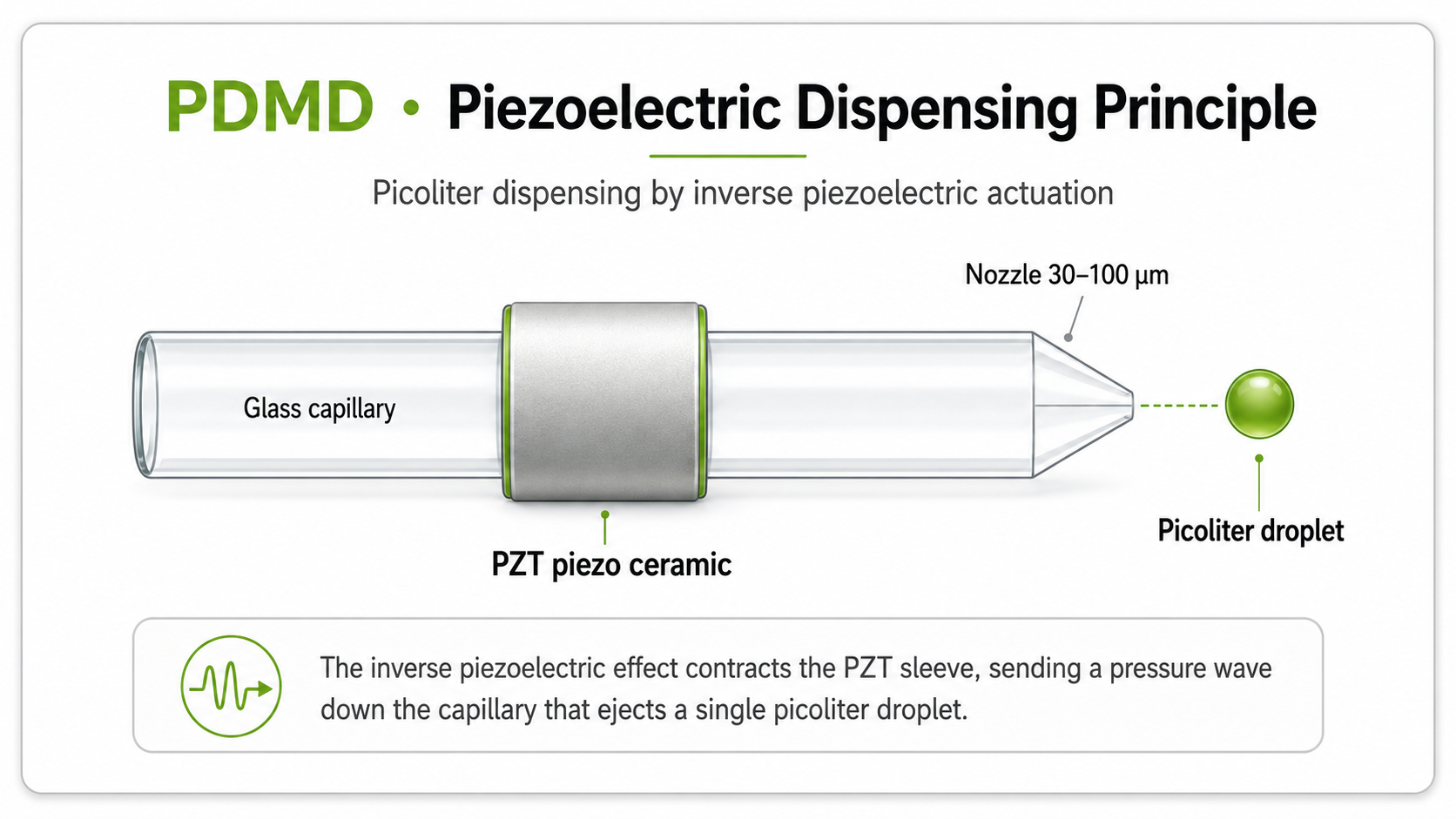
The PDMD is a piezo-driven microdispenser for non-contact picoliter dispensing. It uses a liquid-filled glass capillary, a PZT piezo ceramic and a precision nozzle to generate controlled droplet ejection.
A PZT piezo ceramic surrounds the glass capillary. When the ceramic contracts, it sends a pressure wave through the liquid column toward the nozzle. At the nozzle, the meniscus is pushed outward and a picoliter droplet can detach.
Key elements: glass capillary, PZT piezo ceramic, nozzle in the micrometer range, pressure wave propagation and picoliter droplet ejection.
Droplet formation: from pressure wave to spherical drop
Generating a single, well-defined picoliter droplet requires precise control over several physical processes. If pressure, timing, nozzle geometry or liquid properties are not matched, the result may be no ejection, unstable jetting, satellite droplets, double droplets or unwanted tails.
1. Voltage pulse onset and piezo deformation
The electrical pulse is applied to the piezo ceramic. The ceramic contracts radially and compresses the capillary cross-section. This creates a rapid pressure increase in the liquid column. The resulting pressure depends on pulse amplitude, actuator design, liquid compressibility and capillary geometry.
2. Pressure wave propagation
The compression wave travels through the liquid column toward the nozzle. In water-like liquids, the speed of sound is approximately 1,480 m/s. Reflections from the nozzle and reservoir create an acoustic response in the capillary. This is why pressure wave timing and pulse shape are critical for stable dispensing.
3. Meniscus extrusion and ligament formation
When the pressure wave reaches the nozzle, it pushes the meniscus outward. If the acoustic pressure exceeds the capillary pressure at the nozzle, a liquid ligament is extruded.
Laplace pressure at the nozzle
The pressure required to overcome surface tension at the nozzle can be described using the Laplace pressure:
ΔP = 4γ / d
In this equation, γ is the surface tension and d is the nozzle diameter. Smaller nozzles and higher surface tension increase the pressure required for droplet formation.
4. Rayleigh-Plateau breakup and droplet detachment
The extruded liquid ligament becomes unstable because surface tension tends to minimize surface area. This instability, known as Rayleigh-Plateau breakup, causes the ligament to detach and form a droplet. Correctly timed pulse shaping supports controlled ligament pinch-off and reduces the risk of satellites.
5. Free-flight and substrate impact
After detachment, the droplet travels toward the substrate. During flight, droplet velocity, trajectory and angle are relevant quality parameters. On impact, the droplet may spread, remain compact or splash, depending on volume, velocity, surface tension, substrate energy and surface geometry.
Weber number and impact behaviour
The Weber number describes the relation between inertial forces and surface tension during droplet impact:
We = ρv²d / γ
In this equation, ρ is liquid density, v is droplet velocity, d is droplet diameter and γ is surface tension. Lower values generally indicate less spreading, while higher values increase the risk of excessive spreading or splashing.
Key physical parameters governing droplet volume
Picoliter droplet formation depends on the interaction of nozzle geometry, waveform settings, liquid properties and acoustic refill behaviour. The values below are orientation ranges and must be verified with the actual liquid, dispenser configuration and application.
Nozzle diameter
Typical range: 30-100 µm
Nozzle diameter is a primary determinant of minimum droplet size. Smaller nozzles can support smaller droplets but may increase clogging sensitivity, especially with particles, aggregates or high-viscosity liquids.
Pulse amplitude
Typical range: 20-200 V
Pulse amplitude influences piezo displacement and pressure amplitude. Higher voltage can increase droplet volume up to a saturation point, but excessive amplitude may increase satellites, double drops or sample stress.
Pulse duration
Typical range: µs scale
Pulse duration controls how long pressure is applied to the liquid column. Longer pulse segments can support larger droplets, but may also create tails, multiple droplets or unstable meniscus motion if not matched to the capillary response.
Liquid viscosity
Application-dependent
Viscous liquids dampen pressure waves and often require higher pulse energy or adjusted waveforms. The stable process window depends on viscosity, nozzle geometry, surface tension, formulation and dispenser configuration.
Surface tension
γ in mN/m
Surface tension determines the capillary pressure that must be overcome for droplet formation. Surfactants and solvents can reduce surface tension, but may also influence wetting, satellite formation and drying behaviour.
Dispensing frequency
Up to 1000 Hz depending on process
Dispensing frequency is limited by acoustic refill time, meniscus recovery and liquid stability. At high frequencies, residual oscillations can cause volume variation if the waveform is not matched to the capillary and liquid.
Pulse shaping: the key engineering differentiator
Standard piezo dispensers often use a fixed rectangular voltage pulse. Advanced systems, including the M2-Automation PDMD, allow the waveform to be defined more flexibly. This capability is known as pulse shaping or arbitrary waveform generation.
Pulse shaping matters because the capillary behaves like an acoustic resonator. After the initial pressure wave, acoustic reflections create a pattern of constructive and destructive interference. If the next pulse segment amplifies an unwanted oscillation, the result can be satellite droplets, double droplets or volume instability. If the waveform is timed correctly, residual meniscus oscillations can be reduced.
Rise time
Physical role: Defines how rapidly the pressure wave is launched.
Optimisation target:Fast rise can support larger droplets; slower rise may help reduce satellites.
Peak voltage
Physical role: Determines piezo displacement amplitude.
Optimisation target: Use the minimum amplitude needed for reliable ejection while avoiding excessive droplet energy.
Dwell or hold time
Physical role:Defines the duration of maximum displacement.
Optimisation target:Match the hold segment to capillary response and liquid refill behaviour.
Fall time
Physical role: Controls pressure relaxation and suction behaviour.
Optimisation target: Shape ligament pinch-off, tail behaviour and meniscus recovery.
Bipolar or cancellation pulse
Physical role: Can suppress residual meniscus oscillation.
Optimisation target: Time the segment to reduce acoustic interference and damp satellites.
Dispensing different sample types
Each sample class requires a different pulse optimisation strategy. The examples below are practical starting points for method development. Actual values must always be verified experimentally, because real sample composition, additives, concentration, surface tension and temperature can vary.
Water and aqueous buffers
Water-like buffers usually have low viscosity and relatively high surface tension. They often support stable droplet generation with moderate pulse amplitude and fast rise time, but evaporation can influence concentration during long runs.
Salt and reagent buffers
Higher salt or reagent concentration can change viscosity, surface tension and crystallisation behaviour at the nozzle. These samples may require adjusted pulse energy and careful monitoring of nozzle condition.
Antibody and protein solutions
Protein-containing liquids can be shear-sensitive and may adsorb to surfaces. Gentle waveform settings, controlled droplet velocity and suitable buffer formulation can help preserve biological activity.
Low-surface-tension liquids
Solvents, surfactants or additives can lower surface tension and make ejection easier. At the same time, they may increase wetting, change contact angle or raise the risk of satellite formation.
Viscous and glycerol-containing solutions
Viscous liquids dampen acoustic pressure waves and may require higher amplitude, longer rise time or modified waveform segments. The upper feasible range depends strongly on nozzle size, liquid composition and process requirements.
Cell and bead suspensions
Suspensions require homogeneous particle distribution and suitable nozzle dimensions. Particles, beads or cells should be significantly smaller than the nozzle diameter to reduce clogging risk.
Droplet quality monitoring and auto-tuning
Even with optimized pulse shaping, dispensing conditions can change during a real run. Reservoir evaporation can alter concentration and viscosity, temperature changes can shift surface tension, and nozzle wetting can change contact angle over time.
Professional microdispensing systems therefore use droplet monitoring to observe droplet formation directly. In stroboscopic imaging, a camera is synchronized with the dispensing pulse. By changing the strobe delay, successive images can show droplet formation, flight path and stability.
Image analysis can be used to assess droplet diameter, approximate volume, velocity, travel angle and the presence of satellite droplets. Deviations outside a defined tolerance can trigger a warning or guide further parameter optimisation.
InDot software on M2-Automation instruments supports parameter development by varying pulse amplitude and duration across a defined range and using droplet images to identify stable settings. This can reduce manual optimisation effort, especially when working with new or challenging sample types.
Volume verification from stroboscopic images
If a droplet is approximately spherical in flight, its volume can be estimated from the imaged droplet diameter:
V = (π / 6) · d³
For example, a droplet with a diameter of 50 µm corresponds to approximately 65 pL when calculated as a sphere. Image-based volume estimation is useful for process optimisation, but gravimetric verification using a defined number of dispensed droplets remains an important calibration reference.
The agreement between image-based and gravimetric methods depends on camera calibration, optical resolution, droplet shape, thresholding method, evaporation and experimental setup. For this reason, volume data should be validated for the specific liquid and dispenser configuration.
Piezoelectric dispensing in the M2-Automation portfolio
Piezoelectric dispensing is the principle behind the M2-Automation PDMD for non-contact picoliter dispensing. It is particularly relevant when applications require very small droplets, precise spot placement, low sample consumption and adaptable waveform control.
Other dispensing principles are used for different volume ranges and process requirements. Solenoid-driven nanoliter dispensing is relevant for larger droplets and reagent delivery in the nanoliter-to-microliter range. Contact-based pin dispensing can be useful for selected substrates and contact-tolerant spotting processes.
Related reading
Learn more about related microdispensing technologies, application areas and instrument selection.
See the PDMD piezo dispenser in action
M2-Automation PDMD technology combines piezo-driven picoliter dispensing, pulse shaping, stroboscopic droplet monitoring and InDot software support for application-specific parameter development.
Discuss your application
